
![]()
O2 Input 0-5v Modification
Removing your stock Honda ECU's O2 input limitations.
Introduction
Software such as that available on PGM-Fi.org and from
Hondata make use of the Honda ECU's oxygen sensor input
to allow real time display and data logging of wideband
oxygen sensors. This involves feeding the analogue
output of the wideband sensor's controller in through
the stock (narrowband) O2 input. The known relationship
of voltage to AFR is then entered into the software
package you are using to allow it to log a real world
value.
The wideband set-up I purchased a while ago from
Innovate Motorsports features two independent
programmable outputs with a maximum 5v range of
operation. This allows you to set each output to supply
a voltage of 0-5v in almost any linear relationship to
AFR in the controller's operating range, typically
10:1-20:1 AFR. The most logical way to configure the
unit would be 0v for 10:1 and 5v for 20:1, but there is
a limitation with the stock ECU that prevents us from
doing this.
This modification should not be performed unless you
have a specific need to read from 0-5v in your O2 sensor
input.
The Problem
The stock Honda O2 sensor input will only read to a
maximum of around 3.8v, this does not present any
problem when the stock narrowband O2 sensor is used as
hovers about the 1v area in operation. While you could
just configure your WB controller to output from 0-3.8v
from 10:1 to 20:1 AFR, it would be a lot more accurate
if you could read to 5 volts. Another problem is that
many WB O2 controllers (like the AEM, TechEdge etc) do
not allow you to alter the wideband signal output - this
means any AFR above the 3.8v threshold will not be read!
Various people in the past have used op-amps to rescale
the 0-5v output of these wideband controllers to meet
the restraints of the ECU, and while it gets the job
done it would be nice to have everything done properly.
The Solution
To get around this limitation I started tracing the
input stage to for the O2 sensor input, as most other
analogue inputs on the ECU will read to 5 volts. A block
diagram of the O2 sensor input stage of the USDM P28 ECU is
shown below - I have checked many other OBD-1 ECU's and
they all operate in a similar fashion.
Three main components are shown, an Op-Amp (NJM2904),
Multiplexer (Mux) (MC14051) and the ubiquitous 66207, or
more correctly one of the 66207's analogue to digital
converter (ADC) inputs. The diagram is simplified and
only shows what we are concerned with.
Op-Amp - as its name suggests is an amplifier, and
allows the incoming signal to be processed, depending on
its configuration.
The analogue Mux is best thought of as a multi-pole
switch with many inputs and one output (which is fed to
the ADC) as the switching action does not affect the
signal on its way through. The Mux has pins that allow
the ECU's processor to select which input it wants to
read at any one time, and the ECU cycles through all of
the inputs very fast - this allows it to take a snapshot
of many different inputs, with only one ADC input. This
saves money, as what would be one input channel now
becomes many. The time the CPU takes to scan all of
these inputs and get back to the start does not worry us
here, as the signals it is reading do not change fast
enough to be a concern - the CPU "switches" between
inputs very fast compared to the speed of change of the
input signal, so for all intents and purposes its as
good as a direct ADC input.
The ADC is converts the analogue voltage of 0-5v in this
case into a numerical representation of that voltage
that the CPU can understand, and store in its memory.
Notice I say 0-5v - this is because the ADC is actually
configured to read from 0-5v although the O2 input is
processed so to limit the maximum voltage the ADC sees
to 3.8v.
If you want to read more about Op-Amps, Mux's and ADC's
have a search on Google.
The most simple way to find out what the problem is
would be to apply 5v onto the O2 input, and watch for it
becoming altered along the route. That done it was
discovered that the Op-Amp stage was limiting the
voltage seen by the ECU. This being the case I bypassed
the op-amp by lifting a resistor and applied 5v directly
to the Mux, and without much surprise we now see the ECU
reading to 5v (or as close as it will ever get) - great
stuff!
That done, another problem reared its head. I decided to
set the WB up in the car along with the ECU I was
testing with side by side in the garage to check
operation. I set my WB to read 0-5v over a 10-20:1 AFR
range, the engine was started and was getting an approx
14.7:1 reading on the Innovate's LCD, and the same on
the PC after some calibration. However switching to the
graph mode, showed some anomalies - most notably the
huge spikes on the graph? I stopped the engine.....and
with the AFR reading a steady value on the Innovate WB's
LCD - the spikes were still appearing - how could that
be possible? Checking with a fast response voltmeter
revealed the same story which, proved it was something
relating to the wideband controller.
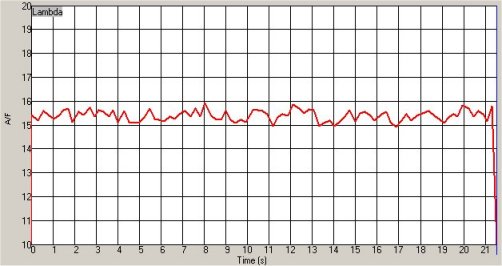
The graph above shows the AFR ratio spiking almost
one whole unit, even though the engine was turned off at
the time!
Next, I powered off the wideband controller took a break
and came back. When I turned the controller back on
again I noticed after the warm up period the AFR kept to
a steady straight line.....for around 20 seconds it
started to oscillate again. Interesting.......it was
fine until just after the initial warm up period.
I decided to get the scope out and take a look at
everything that could be a source for this noise, earth
loops and the like. One of the first sources I thought
the noise could be from, was an inadequate earth on for
the wideband unit itself - my WB gets its supply
directly from an unused accessory terminal on the fuse
box, and a sturdy ground point direct to the body so I
didn't expect to find anything wrong. I also checked the
ground for the analogue output vs. the ECU's O2 input -
again no problems there. However while monitoring the
current drawn by the wideband, I noticed the
fluctuations in AFR were exactly matched to surges of
current drawn by the WB - now this was worth a look! The
WB controller turns on and off the O2 sensor's heater
automatically after the initial warm-up to maintain a
steady temperature - so this was the source of the
fluctuations.
I checked the supply to the WB controller - no voltage
fluctuation on either rail. I internally checked the WB
controller's DAC (Digital to Analogue Converter) also no
fluctuation of the supply rails, so I assume its a
problem with the WB controller's input stage from the O2
sensor, which the scope appeared to point towards.
So, to get round the problem I decided smoothing the O2
input of the ECU would be the easiest approach, I tried
various values of Capacitor/Resistor combination until I
found something that dampened the oscillations, but
would not add lag to the changing input so that the
recorded AFR would be skewed in relation to the actual
AFR the WB controller was seeing. I chose to quickly
modify the input stage as follows:
I added a switch to swap in and out the stock Op-Amp
input stage, and a 10uf capacitor which dampens the
oscillations perfectly almost to the point they are
undetectable yet still gives a very crisp response to
changing input levels.
So, when you want to hook up a wideband you can flick
the switch to use the modified input stage and datalog
as normal, or switch back to the stock input stage with
ease. Of course - the 10uf capacitor can be omitted if
you have a wideband with a noise free output!
Testing with the modified input stage produced excellent
results with recorded and actual AFR's being spot on.